
The operator interacts with printer components to print, maintain, and monitor the state of the printer. This section identifies and explains the functions of the hardware.
 Printer Hardware
|
Component |
Function |
|---|---|
|
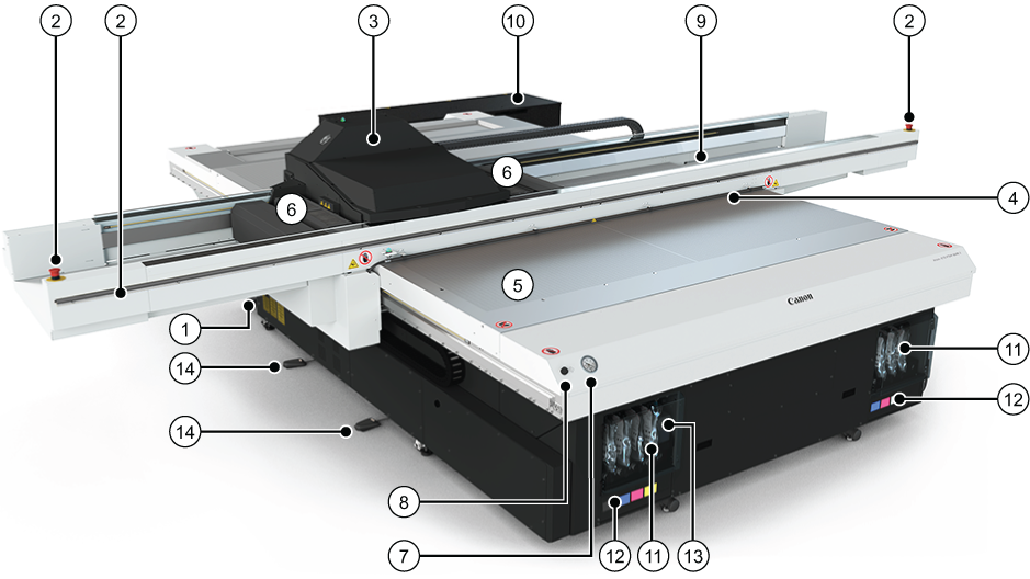
1) Main Power Switch |
Turns the printer On and Off. See also 10) Vacuum Pump Box, which also has a power switch |
|
2) Emergency Stops |
Emergency stops shut down all motion and hazardous systems. Emergency Stop Buttons are installed on both ends of the Gantry and on the User Interface Desk. On either side of the Gantry a stop strip is installed. |
|
3) Carriage |
Carrier for the printheads. |
|
4) Static Suppression System |
Reduces static charge on the media. Results in less ink misting on the printed image. |
|
5) Registration Pins |
Used to register the media. |
|
6) UV Lamps |
Used to cure the ink. |
|
7) Vacuum Gauge |
Displays the level of vacuum securing the media to the table. |
|
8) Print Start Button |
Starts the current print job. |
|
9) Automatic Maintenance Station |
Automatically cleans the printheads. |
|
10) Vacuum Pump Box |
Houses the three vacuum pumps and suppresses the noise from them. The pump box power switch must be On or printer will not work. |
|
11) Ink Bay |
Contains ink bags and the coolant bottle. |
|
12) Ink Filters |
Ink filters are behind a door under the ink bags. The filters remove unwanted particulate matter from the ink. |
|
(13) Coolant Bottle |
Provides coolant to maintain correct temperature of the ink in the printheads. |
|
(14) Foot Pedal Switches |
Turns the vacuum on/off. Can also be used to raise or lower the registration pins. |