
The Operator interacts with printer components to print, maintain, and monitor the state of the printer. This section identifies and explains the functions of the hardware.
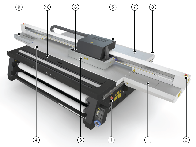 Printer Hardware
|
Component |
Function |
|---|---|
|
1) Main Power Switch |
Turns the printer On and Off. |
|
2) Emergency Stops |
Emergency stop buttons can shut down all motion and hazardous systems. There are three E-stops, one on the Operator Control Station, and one on each end of the gantry. |
|
3) Carriage Guard |
Protects the operator from exposure to UV light and stops all motion if dislodged by an obstacle. |
|
4) Registration Pins |
Allow the operator to register media by placing it against the pins. Registration pin operation can be set at the user interface to work in either manual or automated mode. Pins can be enabled or disabled individually. |
|
5) Printer Status Beacon |
Indicates printer status. See Chapter 3 for details. |
|
6) UV Lamps |
UV light is used to cure the ink. |
|
7) Vacuum Gauge |
Displays the strength of the table vacuum system. If it reads less than 10"Hg, check for vacuum leaks. |
|
8) Print Button |
Starts the current print job. |
|
9) Maintenance Station |
Designated area for cleaning the printheads and the underside of the carriage. |
|
10) Vacuum Zone Control Handles (image 2) 10) on image 1 shows optional RMO |
Five vacuum zone control handles determine if vacuum zones 2 to 6 on the printer table are active when the vacuum pump is switched on. Zone 1 is always on so it has no control handle. The zones on the Arizona 13x0 XT model are different (see Chapter 6 for details). |
|
11) Automatic Maintenance Station (optional) |
Provides a station where printheads can be parked on a vacuum system that pulls debris and particulate matter from the nozzles. |
|
12) Ink Filters |
Remove unwanted particulate matter from the ink. Ink filters are located behind a door under the ink bags. |
|
(13) Coolant Bottle |
Provides coolant to maintain correct temperature of the ink in the printheads. |
|
(14) Vacuum Table Foot Switch |
Toggles the pump that turns the table vacuum on/off. Vacuum must be on prior to starting a print. |
|
(15) Ink Bay |
There are two ink bays: the Primary bay contains CMYK ink and the coolant bottle; the Secondary bay holds any additional supported colour channels. |
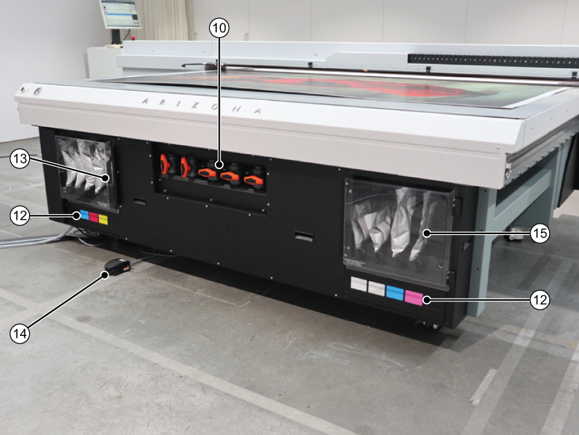 Ink Bays and Vacuum Zone Control Handles