
The Operator interacts with printer components to print, maintain, and monitor the state of the printer. This section identifies and explains the functions of the hardware.
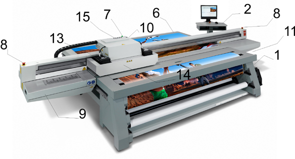 Printer Hardware
|
Component |
Function |
|---|---|
|
1) Main Power Switch |
Turns the printer On and Off. |
|
2) Operator Control Station |
Consists of a podium stand, an LCD display monitor, a mouse, and an emergency stop button. The printer control software is displayed here. |
|
3) Vacuum Zone Control |
Three vacuum zone control handles determine which of the three print zones on the printer table will be active when the vacuum pump is switched on. |
|
4) Vacuum Table Foot Switch |
Toggles the pump to turn the table vacuum on/off. Vacuum must be on prior to starting a print. |
|
5) Vacuum Bleed Valve |
Adjusts the level of vacuum suction applied to the media. Less vacuum reduces artifacts caused by suction when imaging on flexible media. |
|
6) Print Button |
Starts the print job. |
|
7) Printer Status Beacon |
Indicates printer status. See Chapter 3 for details. |
|
8) Emergency Stops |
Shuts down all motion and hazardous systems. See chapter 3 for details. |
|
9) Maintenance Station |
Designated area for cleaning the print heads and the underside of the carriage. |
|
10) Coolant Reservoir |
Provides the ability to monitor and maintain the correct coolant level. |
|
11) Ink Filters |
Ink filters remove unwanted particulate matter from the ink. |
|
12) Ink Bay |
Contains bags of ink with ID tags to ensure that the correct color of ink is installed and not expired. |
|
(13) UV Lamps |
Used to cure the ink. |
|
(14) Carriage Guard |
Protects the Operator from exposure to UV light and stops all motion if dislodged by an obstacle. |
|
(15) Ink Purge Valves |
Allow the operator to isolate specific printheads for purging. |
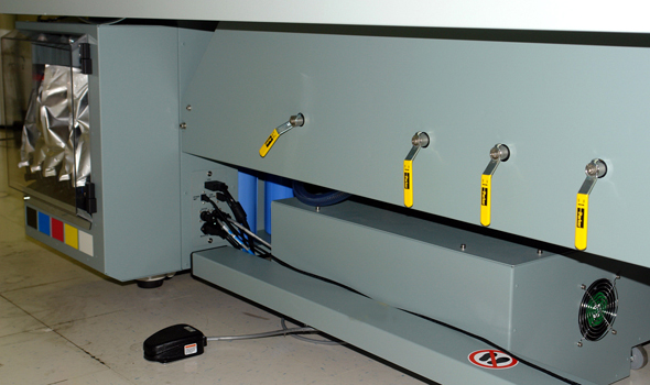 Ink Bay, Bleed Valve, Vauccum Control Handles, and Vacuum Foot Switch
 |