

In prints of some media, a color shift or mottles can appear. You can correct this with the following procedure.
Calibrate the printer.
Calibrate the media family.
Touch .
Select the media from the media catalog.
Touch [Optimize].
Touch the [Determine secondary transfer voltage] procedure.
Select [Small range] in the [Select parameter value range] field to print a small range of patches with secondary transfer voltage parameters.
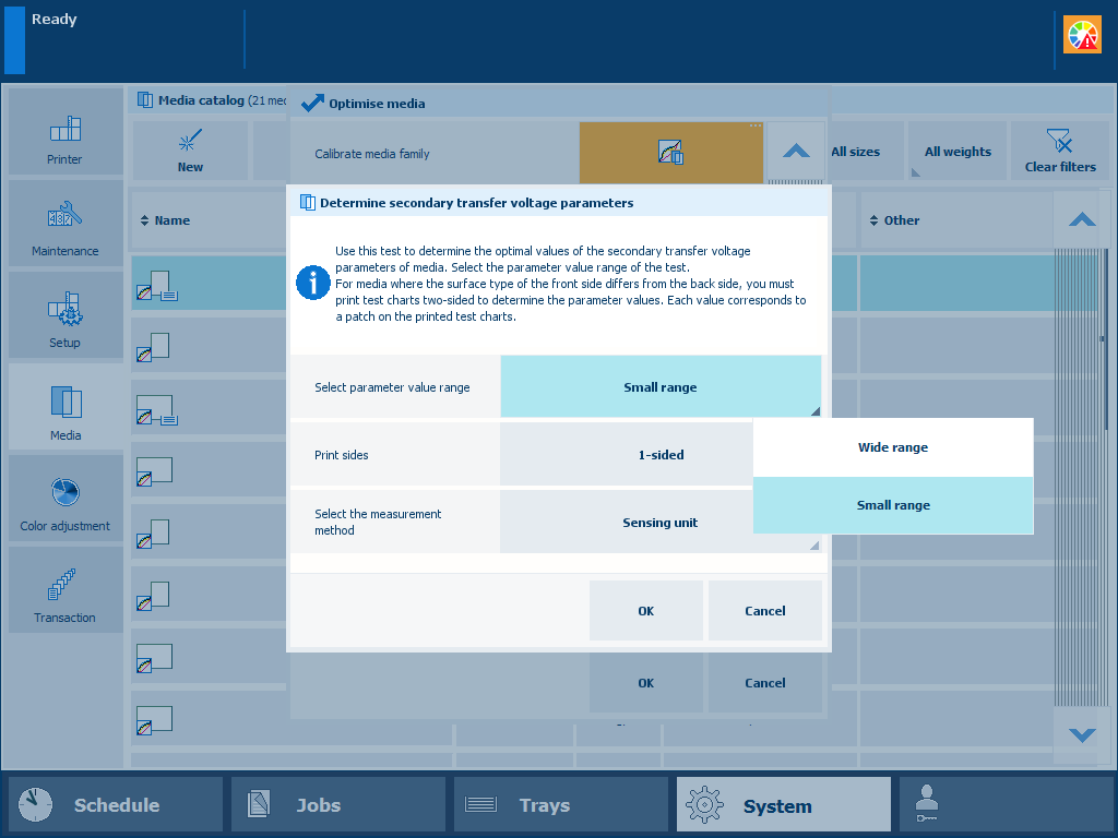 Parameter value range
Select [2-sided] in the [Print sides] field when the surface type of the front side differs from the back side.
Select the measurement method.
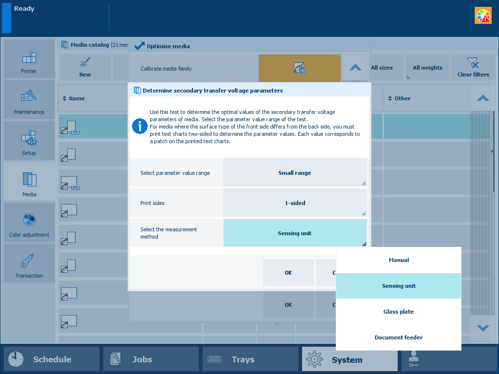 Measurement method
Touch [OK].
The sensing unit performs the procedure automatically. It measures the test charts and automatically adjusts the “Secondary transfer voltage” parameters.
If you use the glass plate or document feeder, you need to place the printed sheets on the glass plate or in the document feeder. The rest of the procedure is performed automatically.
If you chose to determine the secondary transfer voltage parameters manually, continue with the next steps.
Follow the instructions on the control panel.
Take the test charts.
The current values of the secondary transfer voltage parameters are printed in a different color.
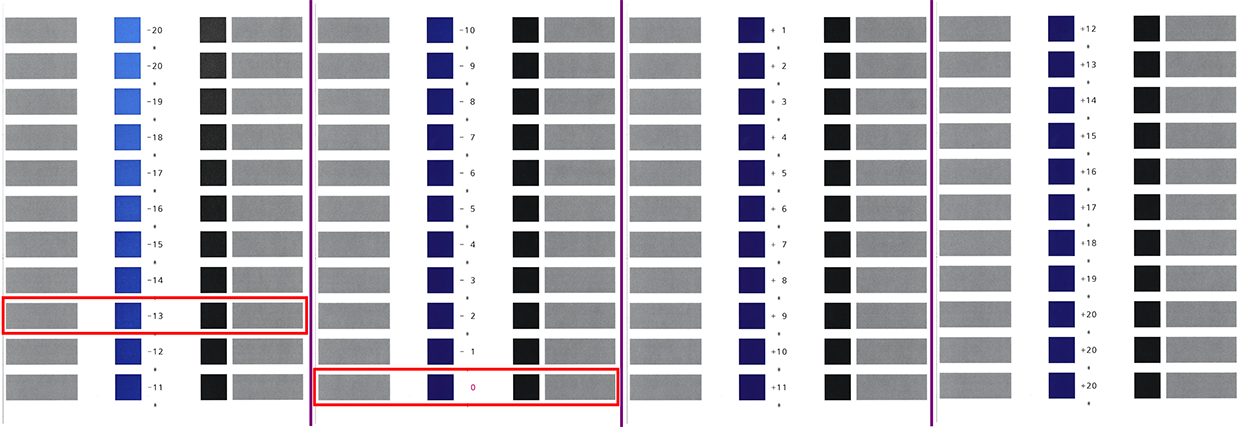 Example of test charts (wide range of patches, A3, 1-sided)
In the above figure is the current value of the secondary transfer voltage parameter 0. The patch with the optimal print quality is -13.
Identify the patches that have the optimal print quality.
When a series of patches show the optimal print quality, take the middle value.
When the patches do not show the optimal print quality, touch [Finish] and redo the procedure with the [Wide range] option.
When you printed 2-sided test charts, examine the front side and back side.
The front side charts shows a single asterisk symbol (*) between the values. The back side charts show two asterisk symbols (**) between the values. The current parameter values are printed in a different color.
Remember the parameter values of the patch with the optimal print quality. In this example: -13.
Touch [Finish] to close the wizard.
Select the[Wide range] parameter in the [Select parameter value range] field to print a wide range of patches with secondary transfer voltage parameters.
Go to: .
Enter the determined parameter value. In this example: -13.
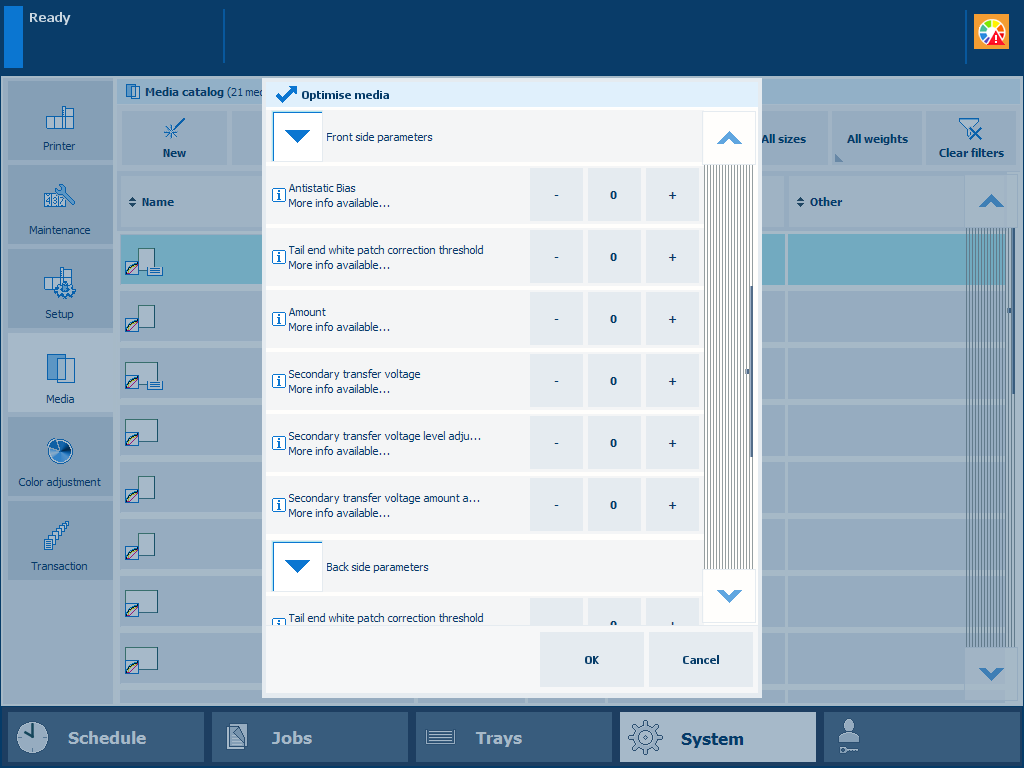 Parameter value for secondary transfer voltage of the front side
Go to: .
Enter the determined parameter value. In this example: -13.
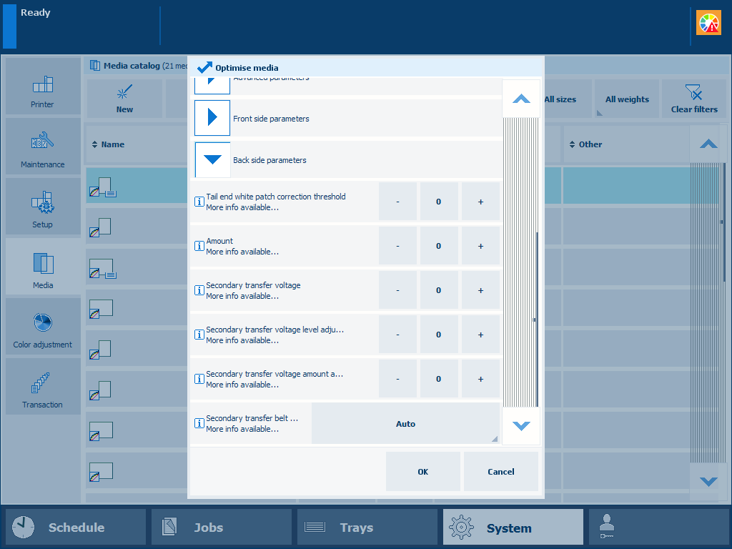 Parameter value for secondary transfer voltage of the back side
Touch [OK] to store the specified values of the secondary transfer voltage parameters.
When you perform the [Determine secondary transfer voltage] procedure without clicking [OK], the specified parameter values are not used.
When you perform the [Determine secondary transfer voltage] procedure again, the new set values of the secondary transfer voltage parameters are printed in a different color.
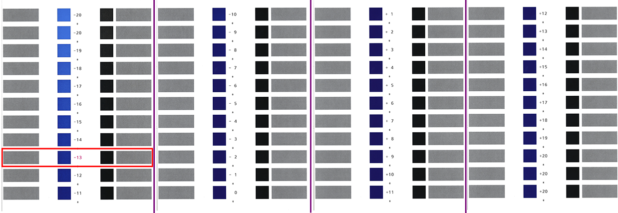 Example of test charts (wide range of patches, A3, 1-sided) where the current parameter value is 0