
In prints of some media, a colour shift or mottles can appear. You can correct this with the following procedure.
Calibrate the printer.
Calibrate the media family.
Touch .
Select the media from the media catalogue.
Touch [Optimise].
Touch the [Determine secondary transfer voltage] procedure.
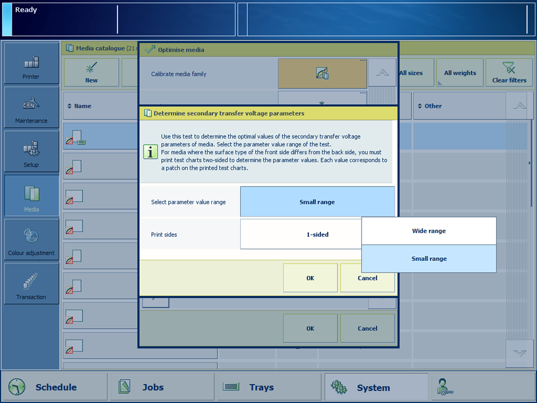
Select [Small range] in the [Select parameter value range] field to print a small range of patches with secondary transfer voltage parameters.
Select [2-sided] in the [Print sides] field when the surface type of the front side differs from the back side.
Touch [OK].
Follow the instructions on the control panel.
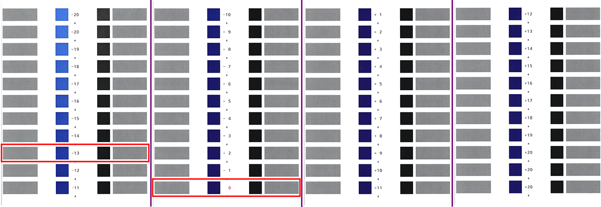
Take the test charts.
The current values of the secondary transfer voltage parameters are printed in a different colour.
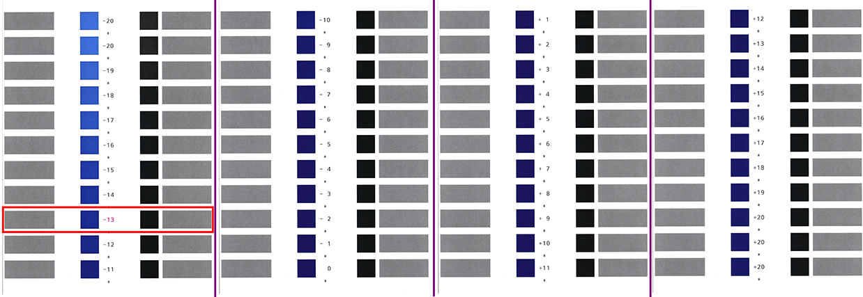
 Example of test charts (wide range of patches, A3, 1-sided)
In the above figure is the current value of the secondary transfer voltage parameter 0. The patch with the optimal print quality is -13.
Identify the patches that have the optimal print quality.
When a series of patches show the optimal print quality, take the middle value.
When the patches do not show the optimal print quality, touch [Finish] and redo the procedure with the [Wide range] option.
When you printed 2-sided test charts, examine the front side and back side.
The front side charts shows a single asterisk symbol (*) between the values. The back side charts show two asterisk symbols (**) between the values. The current parameter values are printed in a different colour.
Remember the parameter values of the patch with the optimal print quality. In this example: -13.
Touch [Finish] to close the wizard.
Select the[Wide range] parameter in the [Select parameter value range] field to print a wide range of patches with secondary transfer voltage parameters.
Go to: .
Enter the determined parameter value. In this example: -13.
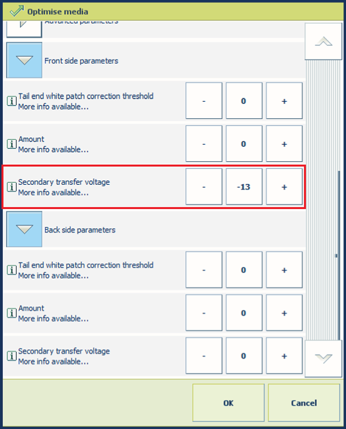 Parameter value for secondary transfer voltage of the front side
Go to: .
Enter the determined parameter value. In this example: -13.
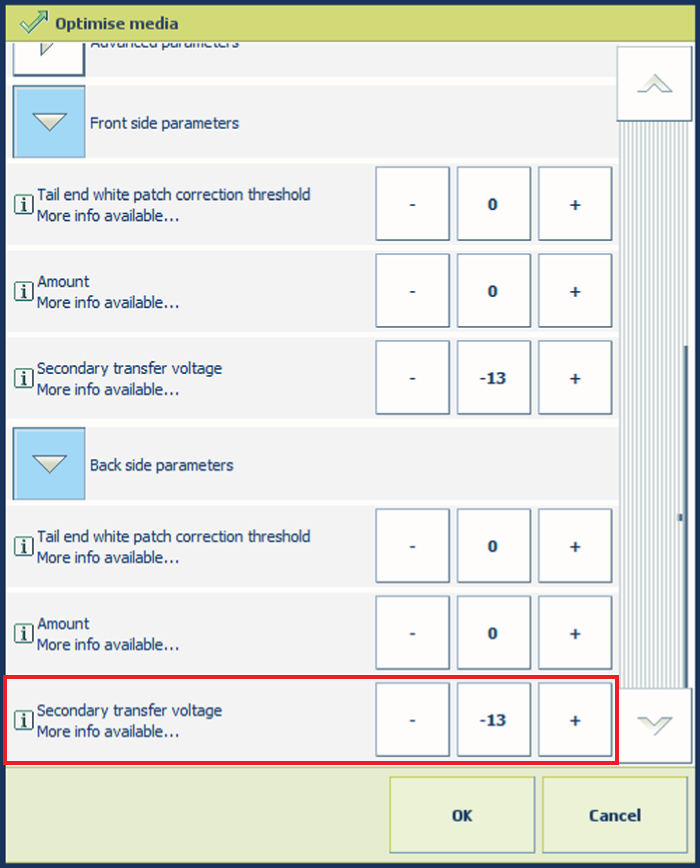 Parameter value for secondary transfer voltage of the back side
Touch [OK] to store the specified values of the secondary transfer voltage parameters.
When you perform the [Determine secondary transfer voltage] procedure without clicking [OK], then the specified parameter values are not used.
When you perform the [Determine secondary transfer voltage] procedure again, then the new set values of the secondary transfer voltage parameters are printed in a different colour.
 Example of test charts (wide range of patches, A3, 1-sided) where the current parameter value is 0.