
The varioPRINT iX-series collects the prints in one or two high capacity stackers. When additional finishing takes place, the prints are transported via the high capacity stacker to the third-party finisher.
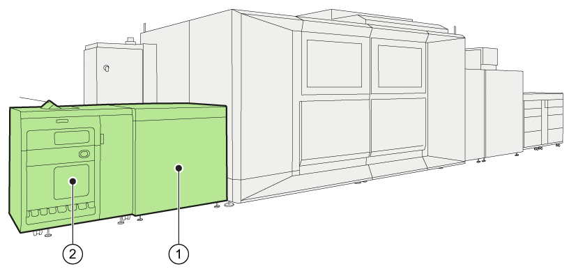 Location of paper output process
 |
Location of the output process |
|
|---|---|
|
1 |
The registration output module transports the prints from the fixation module to the (first) high capacity stacker. |
|
2 |
One or two high capacity stackers collect and eject the prints. |
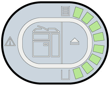
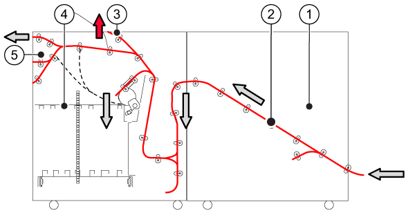 Transport of prints during the paper output process.
|
Description paper path |
|
|---|---|
|
1 |
The registration output module receives the prints. |
|
2 |
The prints are transported to the high capacity stacker. |
|
3 |
Proof prints, calibration charts, quality control sheets, and error sheets automatically arrive in the top tray of the first high capacity stacker. Delivery on the top tray can be useful for small jobs. |
|
4 |
The prints are collected on the stack tray. |
|
5 |
When a DFD (Document Finishing Device) is installed, the high capacity stacker transports the prints to the third-party finisher. |
The high capacity stacker can stack a large volume of prints. The prints are collected on the stack tray. When a stack on the stack tray is completed, the slide door opens and the eject tray with the stack moves out in front of the high capacity stacker. The door closes and the high capacity stacker starts to fill the second stack, the eject tray remains ejected until the prints are removed. The stacking behavior can be altered.
The delivery of long light-weight media in the stacker is improved by air support. By default, the air support setting is enabled. You can disable the air support setting in the Settings Editor when the delivery of long light-weight media is not optimal (, section [Basic] ).
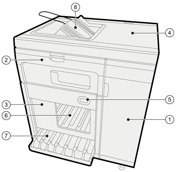 High capacity stacker
|
Description |
|
|---|---|
|
1 |
The front door gives access to the registration unit and the paper path. |
|
2 |
The front cover gives access to the flip rings and the paper path. |
|
3 |
The slide door protects the stacks. |
|
4 |
The top cover gives access to the paper path. |
|
5 |
The control panel shows the filling level and has a button to eject the stack manually. |
|
6 |
The stack tray collects the prints. |
|
7 |
The eject tray presents the finished stack outside the high capacity stacker. |
|
8 |
The top tray collects the prints of small jobs, proof prints, and error sheets. |
The table below describes the stacking behavior of the high capacity stacker.
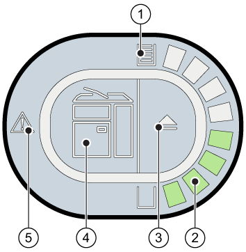 Control panel of the high capacity stacker
|
|
Description control panel |
|---|---|
|
1 |
The full tray indicator indicates the status of the stack tray. 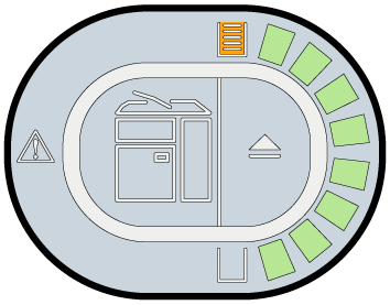
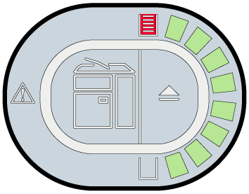 1. Stack is ejected soon. 2. Stack is ejected.
 |
|
2 |
The stack height indicator indicates the filling level of the stack tray. 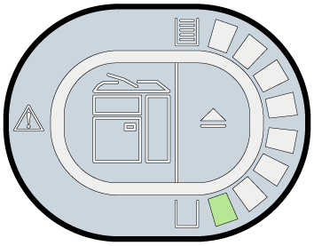
 1. Stack tray is filled. 2. Stack tray is full.
 |
|
3 |
The eject button enables a manual stack eject. The attention light of the eject button indicates the progress of a stack eject.
|
|
4 |
The error location indicator shows the location where an error occurred. 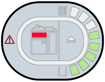
|
|
5 |
The error indicator informs that an error occurred. |