
The varioPRINT iX-series is a modular printer. The modules in the front position are mainly used for the job production. The modules in the rear position give access to the consumables, service units, and control units.
The varioPRINT iX-series can have up to three paper input modules and one or two high capacity stackers. More equipment can be connected to the printer for finishing the output.
Below is an overview of the main parts visible from the control panel of the printer.
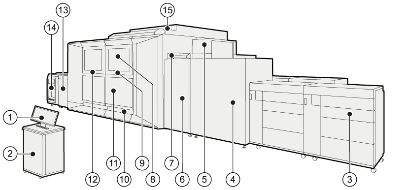 Front view of the printer
|
Description of main hardware parts |
|
|---|---|
|
1 |
The operator desk and the control panel are the local communication point for the operator. |
|
2 |
PRISMAsync Print Server steers the performance, workflow, and print quality of the printer. |
|
3 |
Up to three paper modules hold and feed the media. The paper modules keep the loaded media in optimal condition. |
|
4 |
The paper path module positions the media correctly on the paper path and turns the sheets before the second sides are printed. |
|
5 |
The sentry detects sheets with imperfections, such as waves, bursts, and folded corners. |
|
6 |
The registration input module positions the media correctly on the paper path and purges sheets with imperfections. |
|
7 |
The sentry tray collects sheets with imperfections detected by the sentry. These sheets do not enter the print module. |
|
8 |
The print module holds the ink print heads and the print belt. |
|
9 |
The print belt in the print module uses the suction air technique to ensure that sheets remain flat under the printheads. |
|
10 |
Cooling units decrease the temperature of sheets to prevent them from blocking. |
|
11 |
The post fixation unit gives the sheets a very hot shot of humid air. This results in a smooth and homogenous ink layer with high robustness. |
|
12 |
The fixation module with the fixation drum dries the ink while the suction air technique ensures that sheets remain flat on the fixation drum. |
|
13 |
The registration output module brings the paper path to the height of the high capacity stacker and correctly transfers the prints. |
|
14 |
One or two high capacity stackers collect and stack the prints. When the printer is attached to a third-party finisher such as a booklet maker or a perforator, the DFD (Document Finishing Device) interface kit connects the finisher to the high capacity stacker. |
|
15 |
The air supply unit connects the conditioning module with the print module. |
Below is an overview of the parts visible from the rear side of the printer.
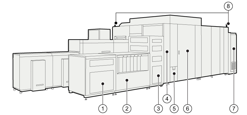 Rear view of the printer
|
Description of main hardware parts |
|
|---|---|
|
1 |
The chiller module optimizes the temperature within the printer. |
|
2 |
The ink cabinet stores the ink, ColorGrip and maintenance liquid containers. The control panel on top of the module is used by the Service organization. |
|
3 |
The control module contains the controllers that steer the print process and the RIP units that process the print data. |
|
4 |
The conditioning module controls the climate in the print module. |
|
5 |
The waste compartment stores the waste ink and ColorGrip containers. |
|
6 |
The maintenance module keeps the printheads in optimal condition. |
|
7 |
The power module is responsible for the power management. |
|
8 |
The operator attention light displays the status of the printer (green, orange, or red). |