
The print module had several ports and connectors to connect it to optionals and other equipment. Access the print module when a paper jam occurs or to perform maintenance tasks.
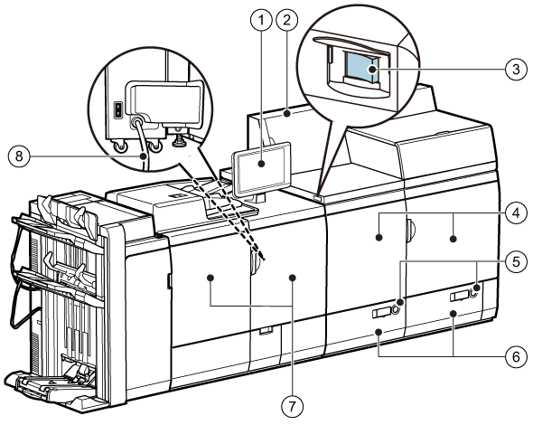 External view of the print module
|
Description print module |
|
|---|---|
|
1 |
Control panel, to operate the print system and to perform daily tasks and maintenance. |
|
2 |
Power supply unit, to provide power to the marking engine and fixing station. |
|
3 |
Main power switch, to turn on the print module. |
|
4 |
Marking engine covers, to access the paper path when a paper jam occurs. |
|
5 |
Buttons, to open the paper trays. |
|
6 |
Internal paper trays, to hold the media. |
|
7 |
Fixing station covers, to access the paper path when a paper jam occurs. |
|
8 |
Power cord, to supply the main power for the print module and automatic document feeder. |
 Internal view of the
Marking engine
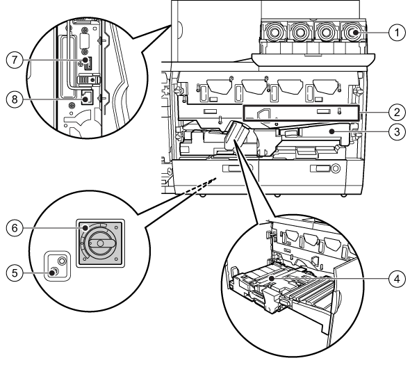
Internal view of the
Marking engine |
Description marking engine |
|
|---|---|
|
1 |
Toner cartridges. |
|
2 |
Intermediate transfer belt, to access the paper path when a paper jam occurs. |
|
3 |
Feeding unit, to access the paper path when a paper jam occurs. |
|
4 |
Skew correction roller, to access the paper path when a paper jam occurs. |
|
5 |
Button, to test the circuit breaker. |
|
6 |
Circuit breaker, to detect an excess current or a leakage current. You access the circuit breaker via the rear side of the print module. |
|
7 |
LAN port, to connect the print module to the print server. |
|
8 |
Data ports, to connect the print module to the print server. |
 Internal view of the
Fixing station
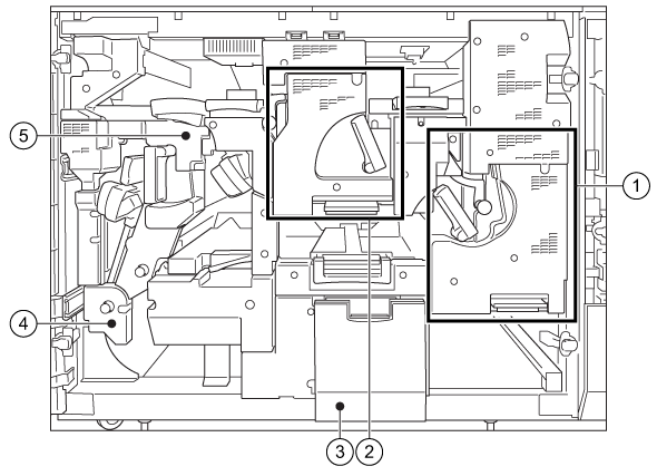
Internal view of the
Fixing station |
Description fixing station |
|
|---|---|
|
1 |
Primary fixing unit, to access the paper path when a paper jam occurs. |
|
2 |
Secondary fixing unit, to access the paper path when a paper jam occurs. |
|
3 |
Replaceable waste toner container, to collect wasted toner. |
|
4 |
Reverse unit, to access the paper path when a paper jam occurs. |
|
5 |
Decurler unit, to access the paper path when a paper jam occurs. |