|
Create a simulation profile which specifies the input space of the Device Link
|
-
Open the Settings Editor and go to: .
-
Click [Import].
-
Browse to the input profile (.icc file) of the simulated printer.
-
Define a unique name and the description.
-
Click [OK].
|
|
Create a composite output profile with a normal output profile
|
-
Open the Settings Editor and go to: .
-
Click [Import].
-
Browse to the storage location of the output profile (.icc file).
-
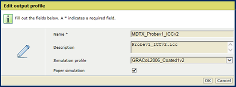
In the [Import output profile] dialog:
-
Define a name and description of the output profile.
-
Select one of the available input profiles, that represents the input profile of the simulated printer or offset press.
When you select [None], device simulation is turned off and a normal output profile is created.
-
Use the [Paper simulation] check box to enable paper simulation, for the selected simulation profile. When you paper simulation is enabled, the color of the media on the simulated printer is simulated. If paper simulation is enabled, the absolute colorimetric rendering intent is applied, otherwise relative colorimetric is applied.
-
Click [OK].
The composite output profile, together with its simulation profile are listed in the list of output profiles.
|
|
Create a composite output profile with a Device Link profile
|
-
Open the Settings Editor and go to: .
-
Click [Import].
-
Browse to the storage location of the Device Link (.icc file) of the simulated printer.
-
In the [Import device link] dialog:
-
Define a name and description of the composite output profile.
-
Select the simulation profile which specifies the input space of the Device Link.
-
Click [OK].
The Device Link, with a reference to its simulation profile, is listed in the list of output profiles.
|

 Define a composite output profile